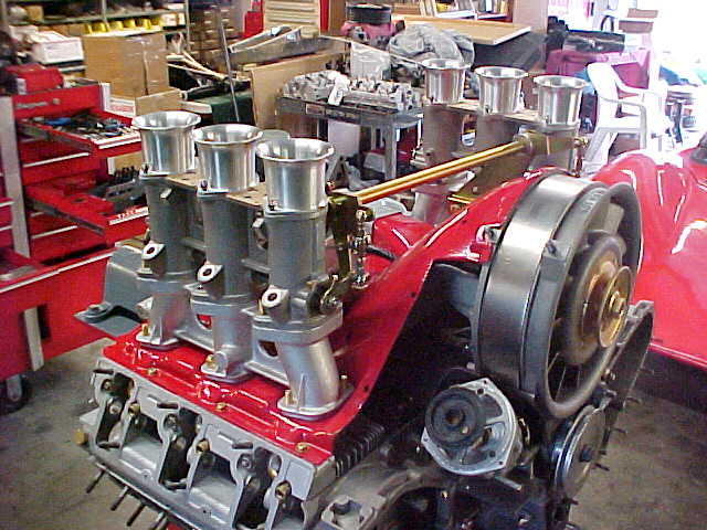
PMO Carburetors have been the choice for Porsche 911 performance enthusiasts since being introduced in 1997. PMO is the original manufacturer of 911 carburetor conversions and we are the only […]
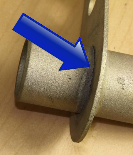
When Powerflex developed PFR57-411 they found there to be a heavy weld on only one-side hence only making one of the parts with an inner chamfer. They did not […]
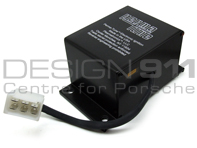
Installation Instructions on how to install a new Porsche 911 6 pin Spark Box or CDI unit. WARNING: HIGH VOLTAGE! DISCONNECT THE BATTERY BEFORE INSTALLING OR SERVICING ANY IGNITION SYSTEMS […]
We offer a wide range of products which we can fit at our London based service centre and body shop. Our specialist team are familiar with fitting complicated products, conversions, […]
An engine oil’s job is primarily to stop all the metal surfaces in your engine from grinding together and tearing themselves apart from friction whilst transferring heat away from the […]
1.Special Tools — In addition to regular sockets/wrenches Non Adjustable Tie Rod End Puller Dull Metal Chisel w/ .5″-.75″ blade width (or big flat head screw driver might work) Silicon […]
Installing the 911 Short Shift Kit Following are detailed instructions on installing a Short Shift into a 1978 911SC. They should be applicable for model years 1974 to 86. Parts […]
Early Heat Exchanger Retrofit. The car used for this upgrade is a 1982 911SC. This upgrade is one of the best bolt on improvements that can be done to 911’s […]
Expandable Oil Return Tube Kits The principle point of failure are the two seals on each end. After many years of service, the seals get old, and begin to leak. […]